
CAN-ASC-2.1 – Outdoor spaces
6. Common accessibility measures
Information
Table of contents
Technical committee members
- Isabelle Ducharme (Chairperson), Chair of the Board of Directors, Kéroul
- Alison Novak (Vice-Chairperson), Scientist, KITE Research Institute, Toronto Rehabilitation Institute – University Health Network
- Andrew Ashby, Manager, Corporate Accessibility & AODA Compliance, Fleming College
- Atul Jaiswal, Ph.D., Research Lead, Perley Health, Ottawa
- Denis Baribeau, Public Works Technician, Inventory and Planning Department, Ministère des Transport du Québec
- Ivy Smith, Associate Landscape Designer, LEES+Associates Landscape Architecture and Planning
- Keiko Shikako, Associate Professor, School of Physical and Occupational Therapy, McGill University
- Kevin Ng, Director of Technical and Program Content, Rick Hansen Foundation
- María-José Aguilar-Carrasco, Researcher, PARCOURS Project, University of British Columbia and Universitat Politècnica de València, València (Spain)
- Marnie Courage, Member/Representative, Canadian Association of Occupational Therapists (CAOT)
- Patricia Longmuir, Senior Scientist, CHEO and CHEO Research Institute
- Peter Stapper, Outdoor spaces consultant
- Robert Lipka, Principal Urban Designer, City of Edmonton
- Taurai Kurebwa, Project Manager, CSA Group
- Trisha Kaplan, Director, Trail Inclusion Initiatives, Trans Canada Trail
6.1 General space requirements
6.1.1 General
Where constructed, all outdoor facilities, surfaces, and furniture shall comply with common accessibility measures outlined in Clause 6.
The requirements for accessibility apply to both paved and unpaved surfaces and to all facilities, whether public or employee-only, in urban, rural, and wilderness settings.
6.1.2 Clear floor space
A clear floor space shall be a minimum of 900 mm (width) by 1500 mm (length). This shall include but is not limited to:
- areas that require access to operating controls and hooks (see Clause 6.5);
- power door operators;
- tactile signage;
- service counters;
- workstations;
- areas adjacent to any tabletops, lavatories, sinks, drinking fountains, or waste receptacles/recycle bins;
- spaces for transferring to benches, equipment, or other facilities; and
- doorways/gates/entrance spaces.
A front approach should be favoured over a side approach. In instances where a front approach is provided at a counter, table, or other working surface, up to 500 mm may be located under the counter.
A side approach that enables a mobility device to be positioned parallel to an object or an item shall have a minimum clear floor space of 900 mm (width) by 2200 mm (length).
6.1.3 Turning space
Where a user is required to perform a turning manoeuvre, there shall be a minimum turning space of 2100 mm by 2100 mm (see Figure 2a).
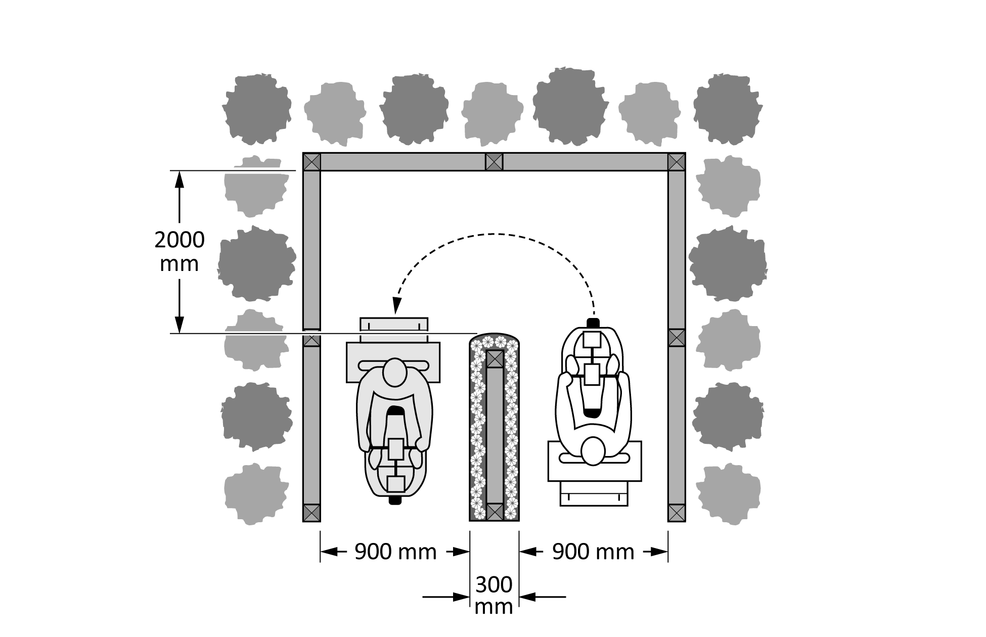
Where a user is required to perform a 180° turn around an obstacle, there shall be a minimum space of 2000 mm by 2100 mm (see Figure 2b).
Figure 2a
Minimum turning space
(See Clause 6.1.3.)
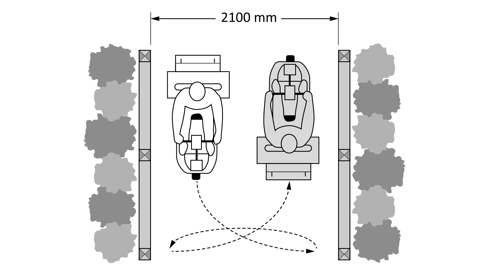
This figure shows a path with the minimum turning space needed for users with assistive mobility devices. The image shows a person with an assistive mobility device travelling on a path that is at least 2100 mm wide, with directional arrows showing how the user would complete a three-point turn to travel in the opposite direction.
Figure 2b
Clear width needed to manoeuvre around a 300 mm wide obstacle
(See Clause 6.1.3.)
6.2 Reach range requirements
6.2.1 Reach range
To accommodate a general reach range for adults (seated or standing), objects shall be mounted between 460 mm and 1100 mm above the surface of the finished floor or ground.
6.2.2 Reach range over an obstruction
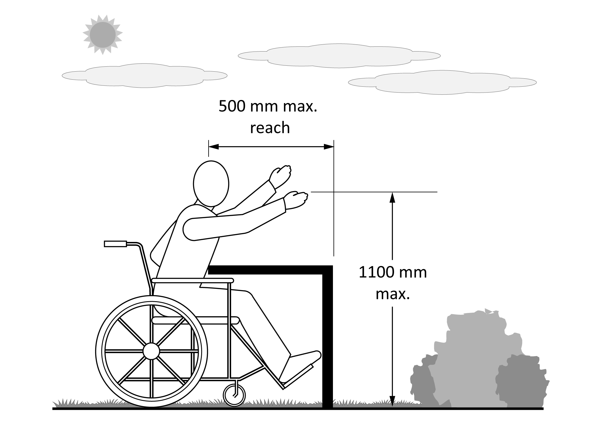
When there is an obstruction, the object shall be located above the top of the obstruction at a height no greater than 1100 mm. The maximum depth of the obstruction should be 500 mm (see Figure 3).
Figure 3
Reach range over an obstruction
(See Clause 6.2.2.)
6.3 Knee and toe clearances
6.3.1 General
Where amenities protrude in a way that make knee/toe clearances necessary, the following provisions shall apply:
- Knee clearances shall be at least 820 mm wide, 280 mm deep, and 685 mm high, and accompanying toe clearances shall be at least 820 mm wide, 430 mm deep, and 230 mm high. Exceptions include tables (including picnic tables), workspaces, or counters where a forward approach is used; in those instances, knee clearances shall be a minimum 820 mm wide, 480 mm deep, and 685 mm high.
- Knee and toe clearances should be oriented to allow access or appropriate use of the facility, including participation with other users.
6.3.2 Knee and toe clearances for children’s facilities
Where play tables, sinks, or other facilities are intended for the use of children, knee clearance of not less than 610 mm high, 430 mm deep, and 760 mm wide shall be provided. The height of rims, curbs, or other obstructions shall not be greater than 785 mm.
Counters, tables, and surfaces designed or constructed primarily for children ages five and under need not provide knee clearance if:
- there is a minimum clear ground space of 760 mm by 1220 mm;
- there is a maximum slope of 1:50 (i.e., 2% slope);
- the approach is arranged for a parallel approach; and
- the height of the rim surface is not greater than 790 mm.
6.4 Doorways, gates, and open entrances
6.4.1 General
A level (maximum 5% slope) and firm surface shall be provided on both sides of a door or gate.
Manoeuvring area on both sides of the door shall be a minimum 1700 mm by 1500 mm, as measured from the inside of the doorway, with 600 mm minimum beside the latch on the pull side.
Where manual or mechanical gates or doorways are provided, they should have a clear opening width that is a minimum of 850 mm and operating controls that comply with Clause 6.5.
Gate hardware operating mechanisms should be mounted at a height of between 460 mm and 1100 mm from the surface or ground.
6.4.2 Space between doors or gates
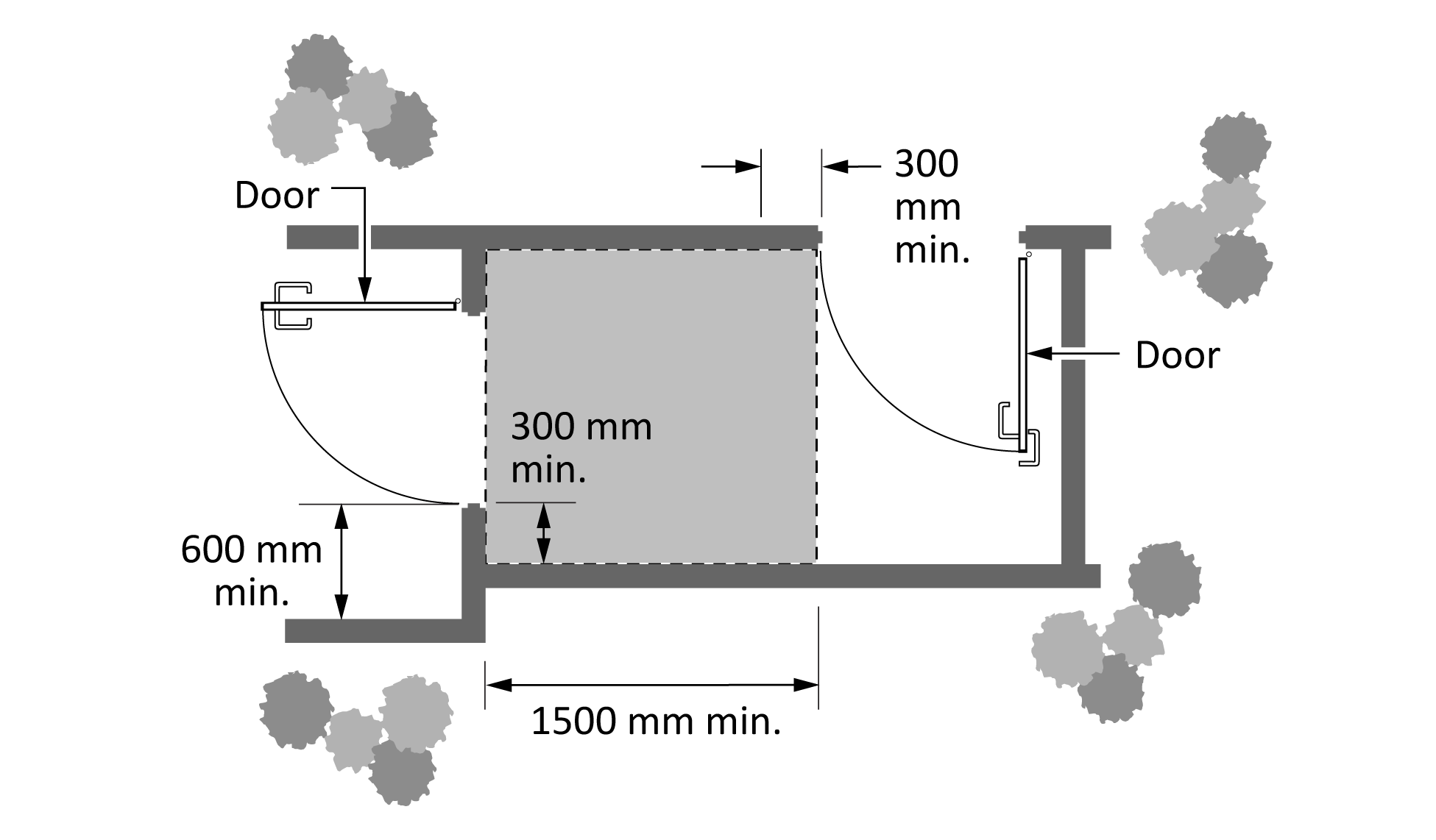
Where two doors or gates are in series, the vestibule area shall provide a minimum of 1500 mm by 1500 mm floor space that is clear of door swings and other obstacles to allow the manoeuvring of mobility aids (see Figures 4a and 4b).
Where doors swing towards the person, at least 600 mm of manoeuvring space beside the latch shall be provided to allow people using mobility aids easy access to the door.
Where doors swing away from the person, at least 300 mm of manoeuvring space beside the latch shall be provided.
Figure 4a
Space between doors or gates
(See Clause 6.4.2.)
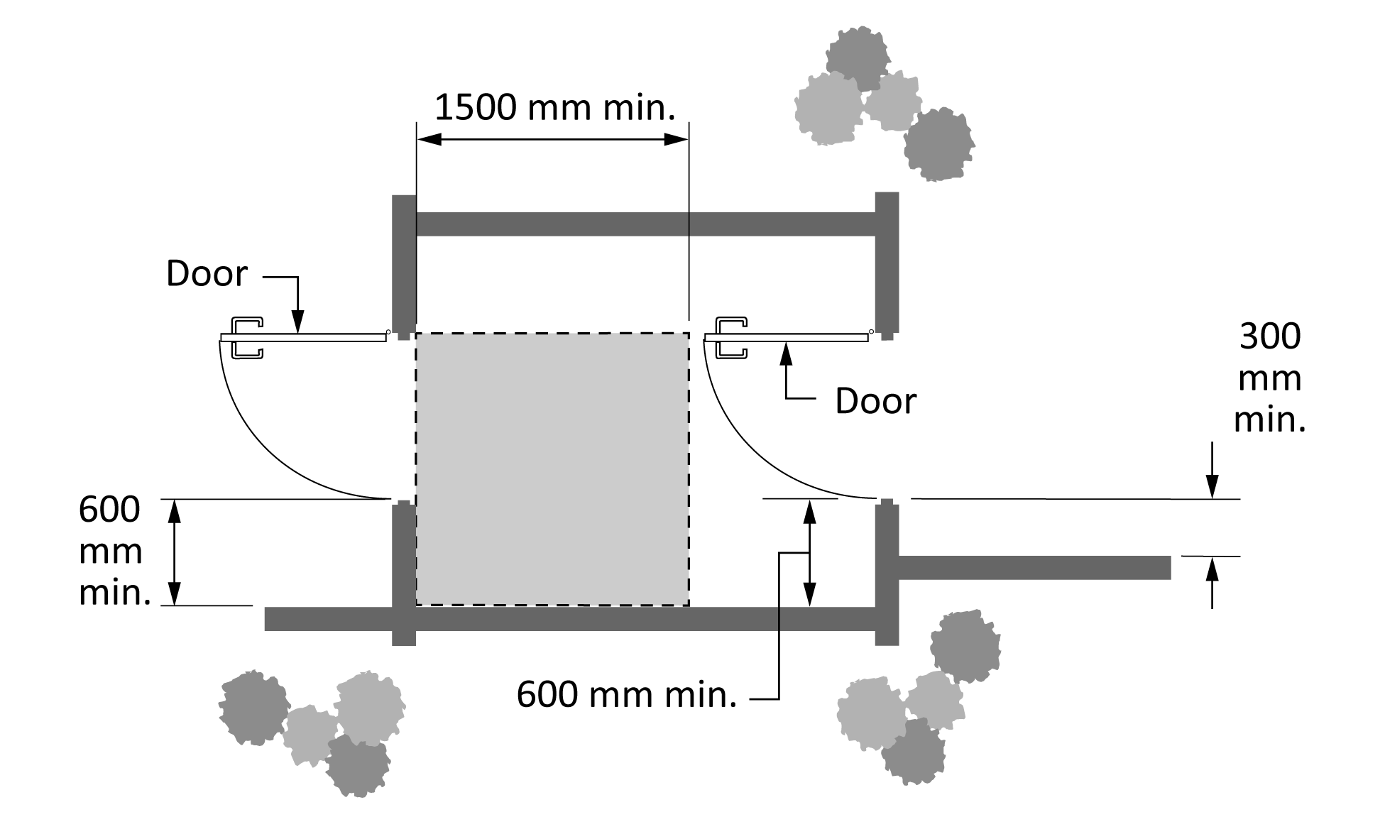
Figure 4b
Manoeuvring area at perpendicular swinging doors
(See Clause 6.4.2.)
6.5 Operating controls
6.5.1 Operability of controls
Clause 6.5 addresses the recognition, accessibility, and operability of operating controls in outdoor environments. Operating controls can include but are not limited to light switches, outlets, alarm pulls, door handles, lever hardware, vending machines/ticket machines, dials, and faucets.
Where supplied, operating controls shall be operable:
- with a closed fist;
- without the need for the user to tightly grasp, pinch, or twist their wrist; and
- with a force of not more than 22.2 N (2.3 kg).
6.5.2 Design and placement
Operating controls:
- shall be luminance (colour) contrasted with the background by at least 70% (see Clause 6.8.3);
- shall be designed so that they do not interfere with features intended to prevent the inappropriate use of the amenities (e.g., by animals or children);
- shall be accessed from a clear floor space to comply with Clause 6.1.2; and
- should be operable from a seated position (see Clause 6.2).
Trash and recycling containers with hinged lids and controls designed to keep out large animals are not required to comply with this Clause.
Notes:
- Wherever possible, controls should be located at the middle of the reach range height requirement (see Clause 6.2).
- Automatic water faucet controls are preferred.
6.5.3 Lighting of controls
The illumination of controls, including liquid crystal displays (or equivalent) that are used as controls and operating mechanisms, shall comply with Clause 6.8.
Note: Many controls have liquid crystal display (LCD) panels that are not backlit, which means for some displays an appropriate amount of front lighting will be needed to enable the user to read the display.
6.6 Seating
6.6.1 Accessible seating and benches
Accessible seating and benches (including seating for picnic tables) shall:
- have a seating/bench surface located at a height of 430 mm to 500 mm above the surrounding grade;
Note: Children might prefer seats as low as 350 mm. These lower benches may be provided in addition to required accessible seating in spaces intended to be used by children. - be 380 mm to 510 mm deep;
- have a level bench with a maximum slope of 1% for drainage;
- provide a backrest or support for at least 50% of the seating positions. Backrests shall extend from a point 50 mm (maximum) above the seat to a point 455 mm (minimum) above the seat;
- provide a minimum clear space in compliance with Clause 6.1.2 for a wheelchair user at the end of a bench, with one side of the space adjoining an accessible route and positioned to allow wheelchair users to be seated shoulder to shoulder with a person seated on the bench;
- have clear space in compliance with Clause 6.1.2 for a wheelchair user at the end of the bench with a surface that is firm and stable, with slope between 2% and 3% in any direction;
- provide a minimum of one armrest that is not located at the end of the bench that abuts the wheeled mobility device parking space;
- should have a luminance (colour) contrast from the surrounding environment and surface colour by at least 70% to comply with Clause 6.8.3;
- have adequate space beneath the bench or seat to allow users to lean forward to stand; and
- for tables, provide adequate clearance underneath for ease of cleaning.
Note: Providing adequate heel space makes rising from a seated position easier. This also provides space for a person to put their feet and bags underneath and potentially even provide a place for service dogs to rest. A variety of bench types accommodates different abilities.
In facilities where only one bench or picnic table is provided, that bench or picnic table shall be accessible. Where there are multiple benches or multiple picnic tables, the number of accessible benches or picnic tables provided shall comply with Clause 7.1.4.
Notes:
- When providing benches or seating, consider surface materials that are appropriate for the climate. In colder climates, select materials that are warmer (e.g., wood) and avoid metal. Surfaces should prevent accumulation of water, snow, and debris.
- In situations where several benches are placed together, benches facing each other or placed at a 90° angle can help persons with hearing requirements to communicate better.
6.6.2 Seating for lifts
Seating for lifts shall consist of a seat that is:
- a minimum of 450 mm wide;
- 405 mm to 485 mm above the floor or ground in its resting position;
- located a minimum 400 mm from (including but not limited to)
- the centre line of the pool lift seat;
- the edge of the pool (for pools);
- the edge of the dock (for docks); or
- the obstacle/edge being negotiated;
- equipped with a footrest;
- equipped with a removable armrest;
- able to sustain a weight capacity of at least 180 kg;
- able to sustain 1.5x the minimum static load; and
- for pools, able to submerge to a maximum depth of 455 mm below the stationary water level.
Note: Lifts can be used in a variety of outdoor environments (e.g., a lift into a boat or a sit ski), so this Clause applies not just to pool environments.
6.7 Accessible table and counter surfaces
6.7.1 Height of top surfaces of accessible tables and counters
The top surface of accessible tables and counters shall be between 730 mm and 860 mm from the floor or ground, or be height-adjustable with operable parts that comply with Clause 6.5.
6.7.2 Clearances and manoeuvring spaces
Knee and toe clearance shall comply with Clause 6.3 where a forward approach is used, or with Clause 6.1.2 where a side approach is required.
The clear floor or ground space provided at each accessible seating space (positioned for a forward approach to the table) shall adhere to Clause 6.1.2.
A clear floor space complying with Clause 6.1.2 shall be provided on two sides of the table, with the path or trail able to overlap a clear floor space at each seating space.
6.7.3 Number of tables/counters
The number of accessible spaces shall comply with Clause 7.1.4 for each type of service, including but not limited to:
- exterior reception desk or lobby;
- security;
- information;
- ticket teller;
- payment; and
- food.
There shall be a minimum of two accessible spaces in high-use areas and where users are anticipated to be served for longer periods of time.
6.8 Illumination and contrast levels
6.8.1 General lighting requirements
All lighting shall:
- provide a clear luminance (colour) contrast (see Clause 6.8.3); and
- be evenly distributed to minimize cast shadows.
6.8.2 Minimum lighting levels
Where lighting is provided for use of a facility outside of daylight hours, the following minimum lighting levels shall be provided during the hours the facility remains open for use (see Table 2):
Table 2
Minimum lighting levels
(See Clause 6.8.2.)
Minimum lighting level | Location |
|---|---|
50 lux | Accessible parking |
30 lux | Main driveway |
Note: See Clause 5.2.2.5 for external signage lighting levels.
Stairs and ramps should be located where there is adequate natural light. If used at night, such as in outdoor amphitheatres or near buildings or campsites, they should have appropriate artificial lighting. Where possible, lighting should come from overhead to shadow the risers and illuminate the treads.
Where provided, outdoor showers shall have lighting that is waterproof and at least 50 lux.
Outdoor lighting should be situated so that light patterns intersect at 2100 mm above ground. Low-level fixtures and posts (below 1500 mm) should be placed to avoid glare. Low-level lighting shall be high enough to clear normal snow accumulation.
Supplementary lighting should be provided to highlight key signage and orientation landmarks (see Clause 9).
Note: Adequate lighting in high-traffic public areas helps facilitate lip reading and sign language communication.
6.8.3 Contrast
When luminance (colour) contrast is required, there shall be a minimum of 70% contrast between the two surfaces/facilities/items/etc., as measured by the Weber contrast equation:
(L1 + 0.05) / (L2 + 0.05)
where
L1 = the relative luminance of the lighter of the colours
L2 = the relative luminance of the darker of the colours
6.9 Sightlines
Safe and independent use of outdoor facilities shall have a clear view of the surrounding environment.
Facilities shall provide the same unobstructed view between 800 mm and 1300 mm above the surface or ground in addition to the unobstructed view provided for a standing adult.
Structures or vegetation shall not obstruct the clear view.
Note: The standing adult sightline is approximately 1500 to 1900 mm.
6.10 Common measures for outdoor surfaces
6.10.1 General
Outdoor surfaces are any surfaces that enable people to circulate throughout outdoor spaces that are found in but are not limited to the outdoor spaces mentioned in Clause 2.1. Outdoor surfaces could be at ground level, above ground level, or below ground level. They may be natural or built materials.
Additional requirements for surfaces specific to trails, beach access routes, playgrounds, docks and water access points, surfaces for accessing outdoor fire pits/cooking facilities/hot ovens, and temporary surfaces can be found in Clause 8.
6.10.2 Exemptions
An exemption for outdoor surface accessibility can occur if the facility meets one or more of the criteria for exemption specified in Clause 2.3.
6.10.3 Firmness
All outdoor surfaces shall be firm under typical user conditions.
Note: A firm surface is one that does not deform more than 20 mm in response to a vertical force of 9 kg per 645 mm2.
6.10.4 Stability
All outdoor surfaces shall be stable under typical user conditions.
Note: A stable surface is one that does not deform more than 20 mm in response to a rotational force of 9 kg per 645 mm2.
6.10.5 Slip resistance
Under dry conditions, all outdoor surfaces shall be slip-resistant unless they are part of a facility intended to provide a sliding experience (e.g., water slide, ice surface for skating).
Note: A slip-resistant surface is one that does not deform more than 20 mm in response to an oblique force of 9 kg per 645 mm2.
6.10.6 Drainage
The drainage of water from the surface shall not affect surface firmness or stability.
6.10.7 Texture
The surface texture should enable a smooth path of travel that does not cause instability or vibration that can affect the user.
6.10.8 Visual patterns and glare
The surface shall create minimal glare and not have strong visual patterning.
6.10.9 Changes in surface texture or type
A change in surface texture or type shall be used to delineate the accessible path of travel. The different surface texture or type should be at least 250 mm in width along both sides of the accessible path.
6.10.10 Use of surface texture or type to convey information
A change in surface texture or type shall be used to indicate to a person who is blind or partially sighted that there is information (e.g., interpretive signage) or facilities (e.g., a bench) available adjacent to the path of travel. The different surface texture or type should extend at least 250 mm in the direction of travel and across the full width of the path.
6.10.11 Slope of outdoor surfaces
6.10.11.1 General
The slope shall be the minimum slope permitted by the terrain and required for drainage. Slope can be in the direction of travel, perpendicular to the direction of travel or at another angle.
6.10.11.2 Measurement
The slope of surfaces is measured as the maximum slope over a 1000 mm distance at any point across the full width of the surface.
6.10.11.3 Maximum slope
The slope shall be less than 1:20 (5%) whenever possible. The maximum slope shall not exceed 1:10 (10%). If one or more of the criteria for exception is met (see Clause 2.3), then the slope may increase to a maximum of 1:7 (14%) for a distance of 1500 mm if the surface is firm and stable.
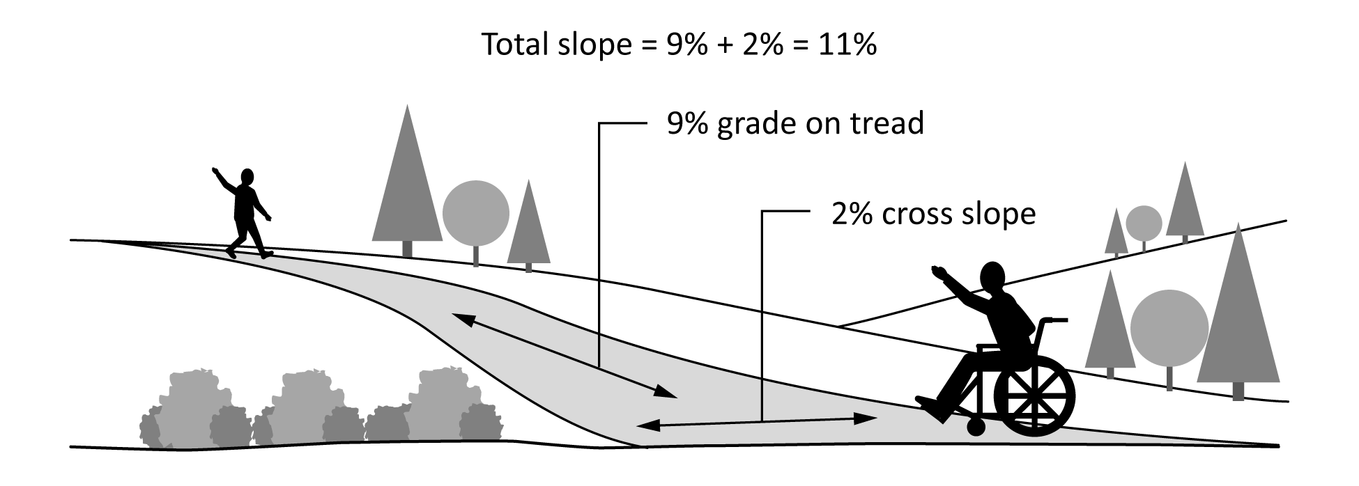
6.10.11.4 Total slope
On paved surfaces, the total of running and cross slopes shall not exceed 8%. The total of running and cross slopes on unpaved surfaces shall not exceed 15% (see Figure 5).
Figure 5
Slope
(See Clause 6.10.11.4.)
6.10.11.5 Rest area
Rest areas shall be provided where the slope exceeds 1:20 (5%). Rest areas are not required for slopes of 1:20 (5%) or less. The maximum interval between rest areas shall be 60 m. All rest areas shall have a slope of less than 1:20 (5%).
Rest areas should be located outside of the path of travel and at least 1500 mm in diameter. The steeper the slope, the more frequent the rest areas should be.
6.10.11.6 Amenities or elements
Where there are amenities or elements intended for use or operation by users, an area shall be provided adjacent to all operating sides of the amenity or element. If the adjacent area has a slope, then it shall have a slope of 1:20 (5%) or less. The adjacent area shall be at least 900 mm in length perpendicular to and 1500 mm in length parallel to the amenity.
Note: “Elements” refers to objects constituting part of an outdoor space, outdoor area, facility, site, etc.
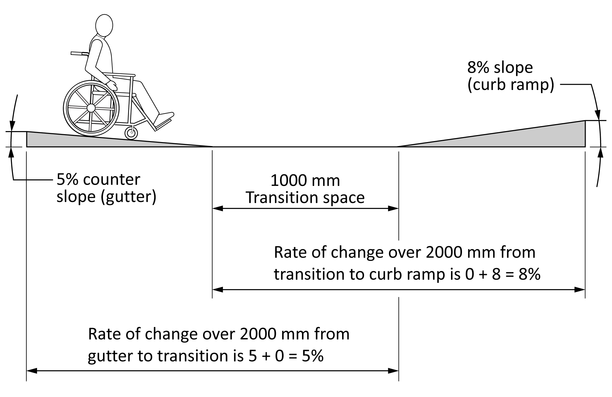
6.10.11.7 Rate of change for slope transitions
The rate of change of slope over a 2000 mm distance shall not exceed 10% (see Figure 6). Rate of change is calculated as the sum of any adjacent slopes (in %) within a 2000 mm distance.
Figure 6
Slope transitions
(See Clause 6.10.11.7.)
6.10.11.8 Provision of information
Information about slopes exceeding 1:20 (5%) should be provided to users before use of the surface is required. Information on alternate routes with lower slope and the direction of travel (i.e., uphill vs. downhill) over slopes exceeding 1:20 (5%) is recommended. Provision of this information shall comply with all wayfinding provisions in Clause 9.
6.10.11.9 Slopes for elevation change
Where the surface has a slope of more than 1:20 (5%) and elevates the user above the surrounding terrain, the elevated section shall be considered a ramp and therefore comply with Clause 6.15.
6.10.11.10 Surfaces within vehicular rights of way
Where the running slope of a vehicular route does not comply with this Clause, the adjacent pedestrian route shall have a running slope equal to or less than the vehicular route.
6.10.11.11 Alternative path of travel
Where slope exceeds 1:20 (5%) on accessible exterior routes, trails, or walkways, stairs and an accessible means of negotiating the elevation change should be provided as an alternative path of travel.
In situations where stairs are provided, the stairs shall not be the only means of access when striving for accessibility of an exterior route, trail, or walkway. The alternative route should be immediately adjacent to the accessible exterior route, trail, or walkway.
Notes:
- Surface slope is important for accessibility. Surface firmness, stability, and slip resistance affect the effort required for a specific slope. Negotiating slopes is particularly difficult for a person using crutches, a walker, or a manual wheelchair.
- Accessibility recommendations typically specify running and cross slope separately because slopes are minimal in most indoor environments and where significant slopes occur (e.g., a ramp) the direction of travel is clearly defined. However, the direction of travel on many outdoor surfaces is highly variable (e.g., sports fields) and turning to look in a different direction can easily change the relative slope. This Standard therefore addresses slope surface and changes in slope surface, regardless of the direction of travel.
- For outdoor surfaces, slope is essential for controlling water flow. Water flow on paved and flat surfaces can be controlled with a 2% slope. As running slope increases, cross slope would also increase to move water off the surface. On unpaved surfaces, high water flow causes erosion and the absorption of water decreases surface firmness and stability.
- Consistent slope over long distances can be fatiguing.
- Transitions between two slopes are areas of risk, particularly for a person using a wheeled mobility device. Sudden changes of slope can jam wheels into an uphill surface or cause the mobility device to tip forward onto a downhill surface. The risk is increased if there is a change in level at the transition between two slopes.
6.11 Clearances on or above outdoor surfaces
6.11.1 Clear width of path of travel
6.11.1.1 General
The minimum clear width is the width of the usable tread at the narrowest point on the surface. Vertical clearance is the distance between the surface and overhead surfaces (e.g., as in caves) or objects (e.g., tree branches, signs).
A clear width path of travel shall be provided to access facilities or furniture, including but not limited to accessible parking, play spaces, picnic tables, benches, potable water sources, dog off-leash areas, sport courts, outdoor assembly areas, waterfront areas, hot springs, and camping facilities.
6.11.1.2 Minimum clear width of path of travel
Outdoor surfaces shall have a clear width of at least 2000 mm to allow people to pass in opposite directions, with the following exceptions:
- The clear width may be reduced to no less than 1200 mm where one or more conditions in Clause 2.3 exist. In areas where the clear width is less than 2000 mm, a passing space at least 2000 mm in width shall be provided at intervals of 100 m.
- This provision does not apply in areas where at least 1000 mm clear width cannot be provided because one or more conditions for departure in Clause 2.3 exist.
- If the surface is limited to travel in one direction or use of the surface is low (i.e., people are unlikely to have to pass others going in the opposite direction), the clear width shall be at least 1200 mm. Passing spaces at least 2000 mm in width shall be provided at intervals of 100 m or line of sight, whichever is longer. The path of travel measurement may be included in the passing space width.
- Fixed queuing guides shall have a minimum clear width path of travel of 1200 mm between posts/tapes. Fixed queuing guides shall also be cane-detectable. Where they require a change in direction, turning space requirements shall comply with Clause 6.1.3.
6.11.2 Protruding objects and vertical clearance
6.11.2.1 Minimum headroom
Objects that protrude into the space above the surface shall provide at least 2050 mm of clear headroom.
6.11.2.2 Detection of reduced headroom
Where vertical clearance is reduced to less than 2050 mm because one or more exemptions in Clause 2.3 exist, a barrier shall be provided to warn people who are blind or partially sighted. The barrier shall be located less than 700 mm above the surface. The barrier shall extend the full width of the area with reduced vertical clearance or at least 400 mm, whichever is less.
Note: Barriers enable reduced overhead clearances to be detected by someone who is blind or partially sighted and navigating with a cane.
6.11.2.3 Reduced headroom information
Where vertical clearance is reduced to less than 2050 mm because one or more exemptions in Clause 2.3 exist and a barrier cannot be provided to warn people who are blind or partially sighted, information about the potential for reduced headroom shall be provided. The information shall be available at the entry point to the surface or facility and made available to potential users prior to arrival.
6.11.2.4 Transit facilities
The clearance from the pavement to the underside of any ceiling structure or hanging object shall be at least 3000 mm at the passenger pick-up area and identified with a sign indicating the clearance height.
6.12 Changes in level and surface openings
6.12.1 Thresholds and changes in level
6.12.1.1 Vertical thresholds and changes in level
Vertical thresholds or changes may be vertical for a change in level of less than 25 mm.
6.12.1.2 Bevelled thresholds and changes in level
Thresholds and changes in level 25 mm to 200 mm shall be bevelled at a maximum slope of 1:3 (33%).
6.12.1.3 Large thresholds and changes in level
Changes in level greater than 200 mm shall be sloped and comply with Clauses 6.15.2 and 6.15.3.
6.12.2 Openings in the surface
6.12.2.1 Maintaining a level surface
Openings in the surface (e.g., grates or spaces between boards on a boardwalk) shall be designed so as not to allow any permitted users or their assistive devices to sink below the level of the surrounding surface.
6.12.2.2 Size of opening
The opening shall not allow passage of a sphere 13 mm in diameter.
6.12.2.3 Elongated openings
Elongated openings shall have the long dimension of the opening perpendicular or diagonal to the direction of travel.
6.13 Curb ramps and crosswalks
6.13.1 Curb ramp
A curb ramp shall be required when the elevation of the vehicular route is different from the elevation of the pedestrian route.
6.13.2 Accessible route
Curb ramps and crosswalks shall be aligned to provide a continuous, clear, and accessible route across the vehicular route.
6.13.3 Surface
The surfaces of curb ramps and crosswalks shall comply with Clause 6.10 except as specified in Clause 6.10.11.4.
6.13.4 Slope of curb ramps and transitions
The slope shall not exceed 1:10 for curb ramps and 1:20 for transitions.
6.13.5 Curb ramp sides
6.13.5.1 Return curb
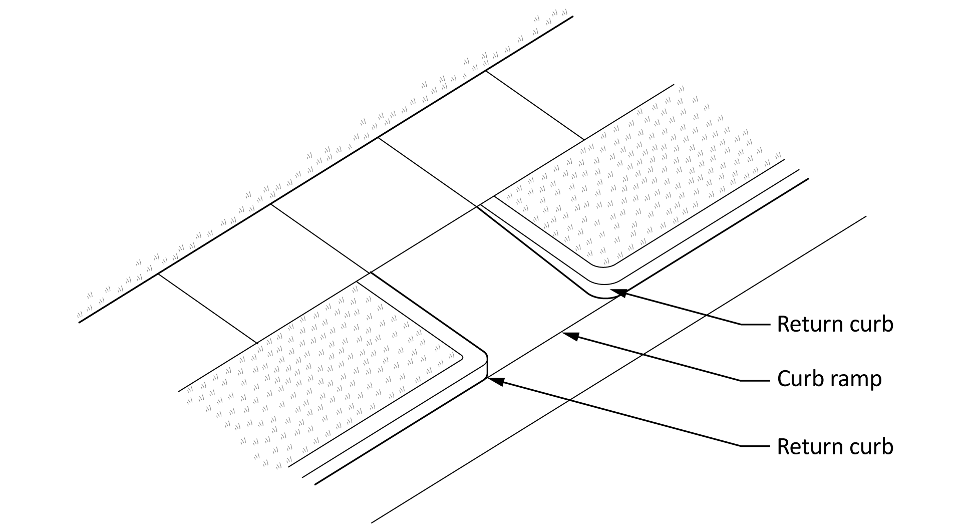
Whenever possible, a return curb shall be used over the full length of the curb ramp to separate the edges of the ramp from the surrounding terrain. The return curb shall have a high tonal contrast of at least 70% and a change in texture at the outside of the return curb to designate it as not intended for pedestrian travel (see Figure 7).
Notes:
- A return curb is an edge that defines both sides of the curb ramp. Return curbs can also provide directional information for those who are partially sighted.
- A change in texture would be if a concrete ramp is surrounded by wood, grass, or any other material.
Figure 7
Return curbs
(See Clause 6.13.5.1.)
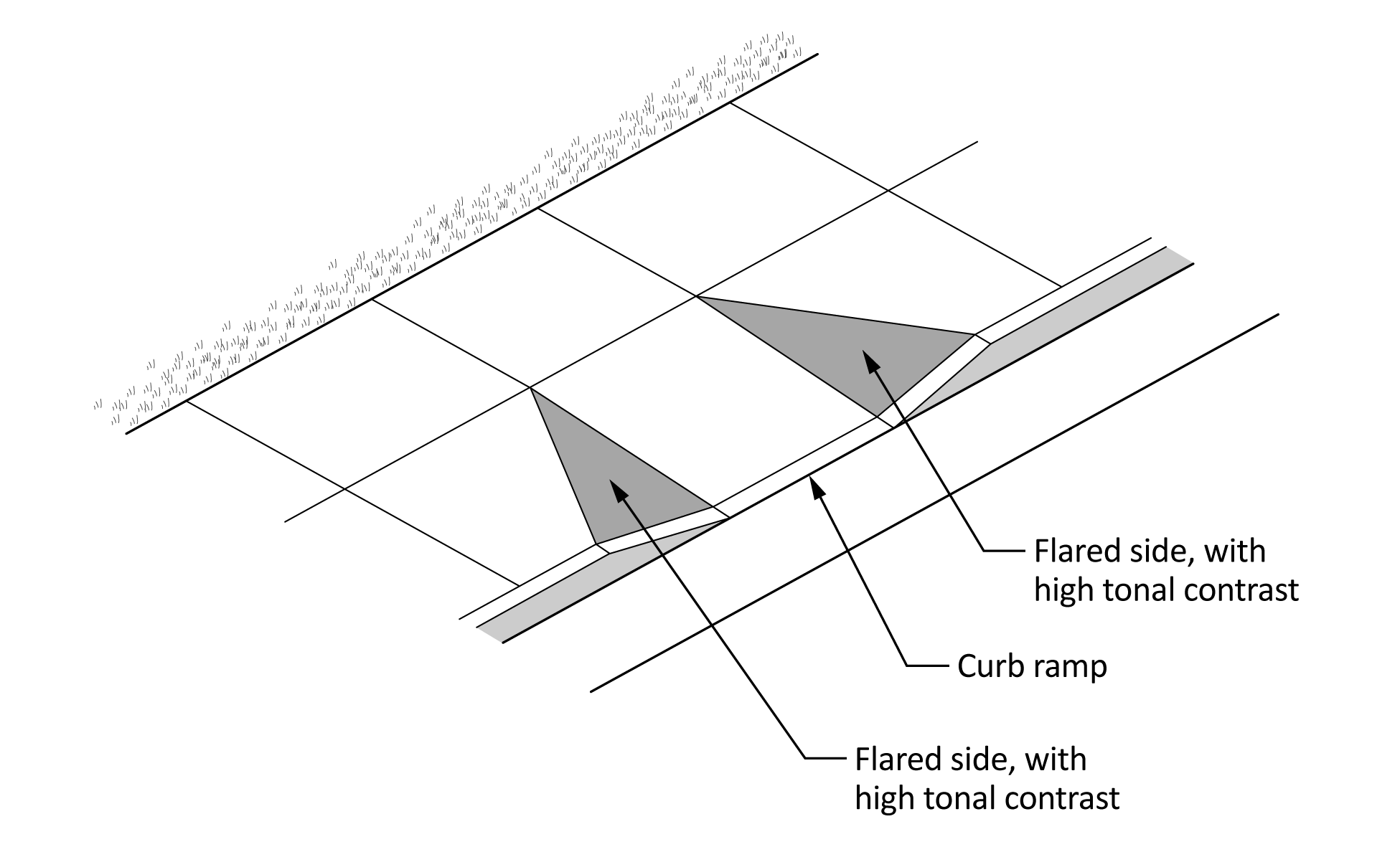
6.13.5.2 Flared sides
Flared sides shall not be permitted for:
- new construction; or
- extensive alteration unless existing infrastructure prevents the installation of a perpendicular or parallel curb ramp design.
When flared sides are the only option, they shall not be steeper than 1:10 (10%). Flared sides shall have high tonal contrast of at least 70% with the ramp and with other surroundings. Flared sides shall be clearly demarcated (see Figure 8).
Note: Flared sides are graded transitions between a ramp and a surrounding sidewalk.
Figure 8
Flared sides
(See Clause 6.13.5.2.)
6.13.6 Alignment
Curb ramps and crosswalks shall be aligned to provide pedestrians with the shortest distance of travel within the vehicular route. Wherever possible, the path of travel should be perpendicular to the vehicular route. Curbs and return curbs shall be used to define and convey the crossing direction.
6.13.7 Location and design of tactile attention indicator surfaces
Curb ramps shall have a tactile attention indicator surface that complies with Clause 9.3.7 to clearly delineate when the pedestrian is moving onto the adjacent vehicular surface. The tactile attention indicator surface shall extend across the full width of the curb ramp and the location of the surface shall comply with Clause 9.3.7.4.
6.13.8 Edge markings
The edges of curb ramps and crosswalks shall be marked by a surface that is permanent, has a high tonal contrast of at least 70%, is of a different texture, and is at least 500 mm in width. Edge markings shall be placed on both edges of the curb ramps and on crosswalks parallel to the direction of travel.
6.13.9 Refuge area
Curb ramps and crosswalks shall provide a refuge area outside of the vehicular route that is a minimum of 1500 mm by 1500 mm in size with a slope not exceeding 1:20 (5%). A refuge area shall be provided as required by the crossing distance, calculated with a pedestrian crossing speed of 0.7 m/s. Refuge areas shall be on an accessible route.
Note: A refuge area provides an area of safety for pedestrians.
6.13.10 Pedestrian bypass
Pedestrian paths of travel for those not entering the vehicular route shall not encroach on the curb ramp or crosswalk.
6.13.11 Drainage
Curb ramp and crosswalk design shall provide for drainage to minimize water or ice accumulation on the accessible route. Drainage structures should not be located in the curb ramp or crosswalk surface.
6.13.12 Sightlines
Curb ramp and crosswalk design shall maintain adequate sightlines for the pedestrian to view the movement of traffic and for drivers to see the pedestrian. Sightlines shall be appropriate for pedestrians who are standing or seated in a mobility device. Parked vehicles shall not reduce the sightlines.
Notes:
- A well-designed curb ramp can be spoiled by an uneven or gapped transition between the road surface and curb ramp. While a smooth transition and minimal slope are ideal for someone using a wheeled mobility device, such smooth transitions are a potential hazard to people who are blind or partially sighted, children, or people with cognitive disabilities who might not recognize the transition from sidewalk to street.
- Poor curb ramp design can present a tripping hazard for ambulatory people or a tipping hazard for people using mobility devices. Further research is needed to address the safety issues associated with all curb ramp designs (including specifications for grooves).
- There is a need to design curb ramps and crosswalks with adjacent free space for snow storage. See Clause 10.5 for more details.
- See Clause 7.15 for accessibility details related to beacons, signal activation, etc.
6.14 Stairs and handrails
6.14.1 General
All stairs except stairs into water (see Clause 6.14.8) shall comply with the provisions in Clauses 6.14.2 to 6.14.7.
6.14.2 Riser height and tread depth
A flight of stairs shall have:
- uniform riser heights and tread depths;
- risers not more than 180 mm high;
- treads not less than 280 mm deep, measured from riser to riser; and
- no open risers.
6.14.3 Tread surface
A flight of stairs shall have treads that are slip-resistant.
The leading edge of a stair tread shall have a durable strip with a high luminance (colour) contrast to the stair tread that is designed to
- extend the full width of the tread;
- be between 40 mm and 60 mm in depth; and
- be luminance (colour) contrasted at least 70% with the tread and riser to comply with Clause 6.8.3.
6.14.4 Nosing
The nosing shall:
- project not more than 38 mm;
- have no abrupt undersides;
- have a radius of curvature at the leading edge of the tread not more than 13 mm;
- where projecting, be sloped to the riser at an angle greater than 60° to the horizontal; and
- have a horizontal strip 50 mm ± 10 mm deep that
- is luminance (colour) contrasted at least 70% with the tread and riser to comply with Clause 6.8.3; and
- extends the full width of the tread.
6.14.5 Tactile attention indicator surfaces and stairs
A tactile attention indicator surface complying with Clause 9.3.7 shall:
- be located at the top of stairs;
- be continuous across the width of the stair with a maximum gap of 75 mm to the stringer or end of the tread;
- have a depth between 600 mm and 650 mm, commencing one tread depth from the edge of the stair;
- be provided at stairs that are not enclosed; and
- be provided at each landing, incorporating an entrance into a stair system where the regular stairway pattern is broken and where the run of a landing with no continuous handrail is greater than 2100 mm.
6.14.6 Stair handrails
Handrails shall:
- be installed on both sides of the stairs;
- be of uniform height, from 860 mm to 920 mm, measured vertically from the leading edge of the tread;
- be continuous around landings less than 2100 mm in length, except where the landing
- is intersected by an alternative path of travel; or
- has an entry door leading onto it;
- at the top of the stairs, extend at least 300 mm parallel to the floor surface;
- at the bottom of the stairs, continue to slope for a distance equal to the depth of one tread and then extend at least 300 mm parallel to the floor surface;
- have the rail extension return to the post or floor; and
Note: This is a potential hazard where there is cross-traffic, particularly for those who are partially sighted. The rail extension should always have to return to the floor or a post so that it is cane-detectable. - be between 24 mm and 40 mm in diameter or maximum cross-section.
6.14.7 Handrails for play spaces
Handrails provided in play spaces shall meet the following requirements:
- Handrails shall be between 25 mm and 40 mm in diameter or maximum cross-section.
- The top of handrail gripping surfaces shall be between 510 mm and 710 mm above the ramp surface.
- Handrails shall not be required at ramps located within ground-level protective surfacing zones. This includes
- ground-level ramps from the play spaces to the defined perimeter edge; and
- ground-level ramps within a play space protective surfacing zone.
6.14.8 Stairs into water
Stairs leading into water shall have:
- a minimum width of 915 mm;
- uniform riser heights (≥ 102 mm but < 153 mm); and
- uniform tread depth (≥ 153 mm).
Handrails should extend 300 mm parallel to the water and should not end abruptly.
6.15 Ramps
6.15.1 General
Ramps shall comply with the provisions of Clauses 6.15.2 to 6.15.8, with the exception that ramps into water shall comply with Clause 6.15.9.
6.15.2 Running slope and length
A ramp shall have:
- a maximum running slope of 1:20 (5%); and
- a horizontal distance between level landings not greater than 9000 mm.
Note: Where one of the conditions for exemption occurs (see Clause 2.3), the running slope of the ramp may be increased to a maximum ratio of 1:12 (8.33%) as long as handrails that have a clear width of 920 mm to 1200 mm between the handrails are provided.
6.15.3 Cross slope
The cross slope of an unpaved ramp surface shall not be steeper than the ratio of 1:20 (5%).
The cross slope of a paved ramp surface shall not be steeper than the ratio of 1:50 (2%).
6.15.4 Width
The clear width on a ramp shall be at least 1200 mm, including the handrails. A level passing space or landing shall be provided every 9000 mm.
6.15.5 Landings
A level landing shall:
- be provided at the top and bottom of each ramp;
- be provided at all changes of ramp direction;
- be at least as wide as the widest ramp leading to it;
- have a length not less than 1500 mm;
- have a width not less than 1500 mm; and
- where it meets a slope change, have a 50 mm ± 10 mm wide luminance (colour) contrasted and slip-resistant strip equal to the width of the ramp that complies with Clause 6.14.3 b).
There shall be a level landing of a minimum area of 1700 mm by 1700 mm at openings and entrances to accessible routes.
Level landings shall include passing spaces that consist of a minimum area of 1700 mm by 1700 mm between two ramp segments of different levels and where there is a turn between two ramp segments.
6.15.6 Surface
A ramp surface shall comply with all provisions of Clause 6, except as noted in Clause 8.
Ramp surfaces shall be flush with adjoining path surfaces available for pedestrian use.
6.15.7 Edge protection
On ramps and landings that are not at grade or adjacent to a wall, protection shall be provided on all edges as specified in Clause 6.16.
6.15.8 Handrails on ramps
Ramps shall have handrails on both sides that:
- are continuous on both sides of the ramp and around landings, except where the landing:
- is intersected by an alternative path of travel; or
- has an entry door leading onto it;
- are luminance (colour) contrasted with their surroundings by at least 70% to comply with Clause 6.8.3;
- have a height between 860 mm and 920 mm, measured from the ramp surface to the top of the rail;
- at the top of the ramp, extend at least 300 mm parallel to the floor surface;
- at the bottom of the ramp, continue to slope for a distance of 300 mm and then extend at least 300 mm parallel to the floor surface; and
- have the rail extension return to the post or floor.
Note: This is a potential hazard where there is cross-traffic, particularly for people who are blind or partially sighted. The rail extension should return to the floor or a post so that it is cane-detectable.
6.15.9 Ramps into water
See Clause 7.10.4.2.
6.16 Edge protection and guards
6.16.1 General
Edge protection or guards shall be provided on surfaces where there is an immediate drop that is between 200 mm and 600 mm adjacent to the surface. Edge protection is not required for a standard road curb.
6.16.2 Surfaces near water
Guards complying with Clause 6.16.4 shall be provided on surfaces adjacent to water that has a depth of at least 600 mm.
6.16.3 Edge protection
Where required, edge protection shall be provided on all edges where the adjacent surface is at least 200 mm above or below the level of the outdoor surface. Edge protection shall have a curb at least 100 mm in height or have railings or other barriers that extend to within 100 mm of the outdoor surface.
6.16.4 Guards
For grade differentials greater than 600 mm, guards shall be provided. Guards shall be vertical and not less than 1070 mm to 1380 mm in height measured vertically to the top of the guard from the adjacent surface. To prevent climbing and maintain safety, a 100 mm sphere shall not pass through the lower 865 mm of the guard system.
6.16.5 Drainage
Edge protection and guards shall be designed so as not to impede drainage of the surface.
6.16.6 Tonal or texture contrast
Where edge protection or guards are provided, the edge protection or guard shall have a luminance (colour) contrast of at least 70% with the surrounding surface to comply with Clause 6.8.3 and/or a texture contrast marking.