EN 301 549 Accessibility requirements for ICT products and services - 8. Hardware
Table of contents for section 8
8.1 General
8.1.1 Generic requirements
The "generic requirements" of clause 5 also apply to ICT that is hardware.
8.1.2 Standard connections
Where an ICT provides user input or output device connection points, the ICT shall provide at least one input and/or output connection that conforms to an industry standard non-proprietary format, directly or through the use of commercially available adapters.
NOTE 1: The intent of this requirement is to ensure compatibility with assistive technologies by requiring the use of standard connections on ICT.
NOTE 2: The word connection applies to both physical and wireless connections.
NOTE 3: Current examples of industry standard non-proprietary formats are USB and Bluetooth.
8.1.3 Colour
Where the ICT has hardware aspects that use colour, colour shall not be used as the only visual means of conveying information, indicating an action, prompting a response, or distinguishing a visual element.
8.2 Hardware products with speech output
8.2.1 Speech volume gain
8.2.1.1 Speech volume range
Where ICT hardware has speech output, it shall provide a means to adjust the speech output volume level over a range of at least 18 dB.
NOTE: Fixed-line handsets and headsets fulfilling the requirements of ANSI/TIA-4965 [i.2] are deemed to comply with this requirement.
8.2.1.2 Incremental volume control
Where ICT hardware has speech output and its volume control is incremental, it shall provide at least one intermediate step of 12 dB gain above the lowest volume setting.
8.2.2 Magnetic coupling
8.2.2.1 Fixed-line devices
Where ICT hardware is a fixed-line communication device with speech output and which is normally held to the ear, it shall provide a means of magnetic coupling which meets the requirements of ETSI ES 200 381-1 [2] and shall carry the "T" symbol specified in ETSI ETS 300 381 [1].
NOTE 1: ICT fulfilling the requirements of TIA-1083-A [i.24] is deemed to comply with the requirements of this clause.
NOTE 2: Magnetic coupling is also known as inductive coupling for T-coil.
8.2.2.2 Wireless communication devices
Where ICT hardware is a wireless communication device with speech output which is normally held to the ear, it shall provide a means of magnetic coupling to hearing technologies which meets the requirements of ETSI ES 200 381-2 [3].
NOTE: ICT fulfilling the requirements of ANSI/IEEE C63.19 [i.1] is deemed to comply with the requirements of this clause.
8.3 Stationary ICT
8.3.0 General
The present document defines the dimensions for accessing stationary ICT that can be placed in a built environment, but does not define the dimensions of the built environment in general.
The scope includes stationary ICT, of which floors and circulation spaces are "an integral part" (typically kiosks and cabins), and where there are external reach ranges relevant for operating the stationary ICT.
Clauses 8.3.2 to 8.3.4 specify mandatory limits for the maximum and minimum height of operable parts and displays. Based on dimensions shown in Figure 53 of ISO 21542:2011 [i.34], it is recommended that the possible height range is reduced to:
- minimum and maximum heights of operable parts: 800 mm and 1 100 mm respectively, and
- minimum and maximum heights of displays: 1 200 mm and 1 400 mm respectively.
8.3.1 Forward or side reach
Stationary ICT shall conform to either clause 8.3.2 or clause 8.3.3.
NOTE 1: This does not preclude conforming to both clauses.
NOTE 2: The dimensions set out in clauses 407.8.3 and 407.8.2 of Section 508 of the Rehabilitation Act, as published in January 2017 [i.25], are identical to those given in clauses 8.3.2 and 8.3.3 of the present document.
NOTE 3: Physical access to stationary ICT is dependent on the dimensions of both the ICT and the environment in which it is installed and operated. Clause 8.3 does not apply to the accessibility of the physical environment external to the ICT.
8.3.2 Forward reach
8.3.2.1 Unobstructed high forward reach
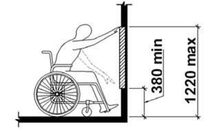
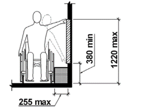
Where no part of the stationary ICT obstructs the forward reach, at least one of each type of operable part shall be located no higher than 1 220 mm (48 inches) above the floor of the access space. This is shown in Figure 2.
8.3.2.2 Unobstructed low forward reach
Where no part of the stationary ICT obstructs the forward reach, at least one of each type of operable part shall be located no lower than 380 mm (15 inches) above the floor of the access space. This is shown in Figure 2.
Figure 2: Unobstructed forward reach
8.3.2.3 Obstructed forward reach
8.3.2.3.1 Clear space
Where an obstruction is an integral part of the stationary ICT and hinders the access to any type of operable part, the ICT shall provide a clear space which extends beneath the obstructing element for a distance not less than the required reach depth over the obstruction.
NOTE: Ensuring that there will be unhindered "access to any type of operable part" guarantees that a user will be able access at least one of each type of operable part.
8.3.2.3.2 Obstructed (< 510 mm) forward reach
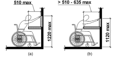
Where the stationary ICT has an obstruction which is an integral part of the ICT and which is less than 510 mm (20 inches), the forward reach to at least one of each type of operable part shall be no higher than 1 220 mm (48 inches) above the floor contact of the ICT. This is shown in Figure 3 (a).
8.3.2.3.3 Obstructed (< 635 mm) forward reach
Where the stationary ICT has an obstruction which is an integral part of the ICT and which is not less than 510 mm (20 inches) but is less than 635 mm (25 inches) maximum, the forward reach to at least one of each type of operable part shall be no higher than 1 120 mm (44 inches) above the floor contact of the ICT. This is shown in Figure 3 (b).
Figure 3: Obstructed forward reach
8.3.2.4 Knee and toe clearance width
Where the space under an obstacle that is an integral part of the stationary ICT is part of access space, the clearance shall be at least 760 mm (30 inches) wide.
8.3.2.5 Toe clearance
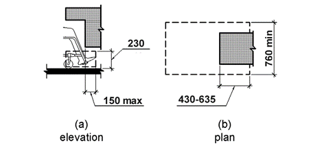
Where an obstacle is an integral part of the stationary ICT, a space under the obstacle that is less than 230 mm (9 inches) above the floor is considered toe clearance and shall:
- extend 635 mm (25 inches) maximum under the whole obstacle;
- provide a space at least 430 mm (17 inches) deep and 230 mm (9 inches) above the floor under the obstacle;
- extend no more than 150 mm (6 inches) beyond any obstruction at 230 mm (9 inches) above the floor.
This is shown in Figure 4.
Figure 4: Toe clearance
8.3.2.6 Knee clearance
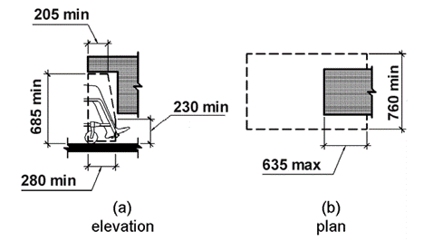
Where an obstacle is an integral part of the stationary ICT, the space under the obstacle that is between 230 mm (9 inches) and 685 mm (25 inches) above the floor is considered knee clearance and shall:
- extend no more than 635 mm (25 inches) under the obstacle at a height of 230 mm (9 inches) above the floor;
- extend at least 280 mm (11 inches) under the obstacle at a height of 230 mm (9 inches) above the floor;
- extend at least 205 mm (8 inches) under the obstacle at a height of 685 mm (27 inches) above the floor;
- be permitted to be reduced in depth at a rate of 25 mm (1 inch) for each 150 mm (6 inches) in height.
This is shown in Figure 5.
Figure 5: Knee clearance
8.3.3 Side reach
8.3.3.1 Unobstructed high side reach
Where the side reach is unobstructed or obstructed by an element that is an integral part of the stationary ICT and which is less than 255 mm (10 inches), at least one of each type of operable part shall be within a high side reach which is less than or equal to 1 220 mm (48 inches) above the floor of the access space. This is shown in Figure 6.
8.3.3.2 Unobstructed low side reach
Where the side reach is unobstructed or obstructed by an element that is an integral part of the stationary ICT and which is less than 255 mm (10 inches), at least one of each type of operable part shall be within a low side reach which is greater than or equal to 380 mm (15 inches) above the floor of the access space. This is shown in Figure 6.
Figure 6: Unobstructed side reach
8.3.3.3 Obstructed side reach
8.3.3.3.1 Obstructed (≤ 255 mm) side reach
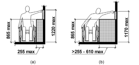
Where stationary ICT has an obstruction which is an integral part of the ICT, the height of the obstruction shall be less than 865 mm (34 inches). Where the depth of the obstruction is less than or equal to 255 mm (10 inches), the high side reach to at least one of each type of operable part shall be no higher than 1 220 mm (48 inches) above the floor of the access space. This is shown in Figure 7 (a).
8.3.3.3.2 Obstructed (≤ 610 mm) side reach
Where stationary ICT has an obstruction which is an integral part of the ICT, the height of the obstruction shall be less than 865 mm (34 inches). Where the depth of the obstruction is greater than 255 mm (10 inches) with a maximum depth of 610 mm (24 inches), the high side reach to at least one of each type of operable part shall be no higher than 1 170 mm (46 inches) above the floor of the access space. This is shown in Figure 7 (b).
Figure 7: Obstructed high side reach
8.3.4 Clear floor or ground space
8.3.4.1 Change in level
Where stationary ICT has a floor within it, then any change of floor level within it or entering it shall be ramped with a slope no steeper than 1:48.
Exceptions:
- If the change in floor level is less than or equal to 6,4 mm (¼ inch) the change may be vertical as shown in Figure 8.
- If the change in floor level is less than or equal to 13 mm (½ inch) the change may have a slope not steeper than 1:2 as shown in Figure 9.
Figure 8: Vertical change in level
Figure 9: Bevelled change in level
8.3.4.2 Clear floor or ground space
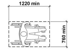
Where stationary ICT has an operating area within it, it shall provide a clear floor area that has the minimum dimensions of 760 mm (30 inches) by 1 220 mm (48 inches) from which to operate the ICT. This is shown in Figure 10.
Figure 10: Clear floor or ground space
8.3.4.3 Approach
8.3.4.3.1 General
Where stationary ICT has an access space inside it, at least one full side of the space shall be unobstructed.
8.3.4.3.2 Forward approach
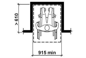
Where the operating area is inside an alcove within the stationary ICT, the alcove is deeper than 610 mm (24 inches), and where a forward approach is necessary, the dimension of the access space shall be a minimum of 915 mm (36 inches) wide. This is shown in Figure 11.
Figure 11: Manoeuvring Clearance in an Alcove, Forward Approach
8.3.4.3.3 Parallel approach
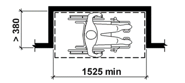
Where the operating area is inside an alcove within the stationary ICT, the alcove is deeper than 380 mm (15 inches), and where a parallel approach is possible, the dimension of the access space shall be a minimum of 1 525 mm (60 inches) wide. This is shown in Figure 12.
Figure 12: Manoeuvring Clearance in an Alcove, Parallel Approach
8.3.5 Visibility
Where stationary ICT provides one or more display screens, at least one of each type of display screen shall be positioned such that the information on the screen is legible from a point located 1 015 mm (40 inches) above the centre of the floor of the operating area).
NOTE: The intent of this requirement is that the information on the screen can be read by users with normal vision and appropriate language skills, when seated in a wheelchair.
8.3.6 Installation instructions
Installation instructions shall be made available for all stationary ICT. These instructions shall give guidance on how to install the ICT in a manner that takes into account applicable requirements for accessibility of the built environment as they apply to the installation of the ICT.
Where there are no such requirements the instructions should require that the dimensions of the installed ICT conform to clauses 8.3.2 to 8.3.5 of the present document.
8.4 Mechanically operable parts
8.4.1 Numeric keys
Where provided, physical numeric keys arranged in a rectangular keypad layout shall have the number five key tactilely distinct from the other keys of the keypad.
NOTE: Recommendation ITU‑T E.161 [i.20] describes the 12-key telephone keypad layout and provides further details of the form of tactile markers.
8.4.2 Operation of mechanical parts
8.4.2.1 Means of operation of mechanical parts
Where a control requires grasping, pinching, or twisting of the wrist to operate it, an accessible alternative means of operation that does not require these actions shall be provided.
8.4.2.2 Force of operation of mechanical parts
Where a control requires a force greater than 22,2 N to operate it, an accessible alternative means of operation that requires a force less than 22,2 N shall be provided.
NOTE: ISO 21542:2011 [i.34]: Building Construction - Accessibility and Usability of the Built Environment recommends a value between 2,5 and 5 Newtons.
8.4.3 Keys, tickets and fare cards
Where ICT provides keys, tickets or fare cards, and their orientation is important for further use, they shall have an orientation that is tactilely discernible.
NOTE: ETSI ETS 300 767 [i.6] defines suitable tactile indications for plastic cards.
8.5 Tactile indication of speech mode
Where ICT is designed for shared use and speech output is available, a tactile indication of the means to initiate the speech mode of operation shall be provided.
NOTE: The tactile indication could include Braille instructions.
